Setting Up Single Signon
This section provides an overview of single signon and remote nodes, and discusses how to:
Define remote nodes.
Identify all trusted nodes.
Adding remote nodes to the integration network.
Testing single signon.
In a PeopleSoft environment, single signon is deployed for a number of reasons. For users, single signon provides the ability for them to navigate freely within a environment of multiple applications after being authenticated only once. For integration of PeopleSoft applications and systems, single signon identifies those systems that are trusted participants in the integration. With unified navigation, single signon is deployed for both purposes: to identify those trusted systems and to allow users to navigate freely to resources on those trusted systems.
The first step to configuring single signon is to define the participating nodes from each content provider system in the portal system, and conversely, to define the default local node of the portal system in each content provider system.
The following diagram illustrates four systems participating in unified navigation: PIH (the portal system), FSCM, and HCM.
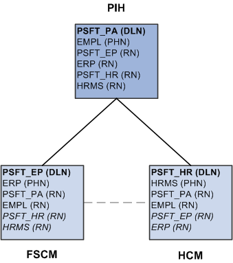
Under each system, the default local node is highlighted in bold and identified with the notation (DLN). For example, on the PIH system, the default local node is PSFT_PA. On the HCM system, the default local node is named PSFT_HR. The portal host nodes are identified with the notation (PHN). On the FSCM system, the portal host node is named ERP. On the HCM system, the portal host node is named HRMS.
Important! Unified navigation supports same portal integration only—for example, EMPLOYEE portal to EMPLOYEE portal, CUSTOMER portal to CUSTOMER portal, or PARTNER portal to PARTNER portal, and so on. However, you should always use the content provider system's portal host node to create remote folders or import pagelets.
Finally, under each system, the remote nodes that need to be defined are identified with the notation (RN). For example, on the PIH system, four remote nodes would need to be defined: PSFT_EP, ERP, PSFT_HR, and HRMS. On each of the content provider systems, two remote nodes would need to be defined at a minimum: PSFT_PA and EMPL.
In addition, if content from one content provider is to be configured as related content on any other content provider, then the applicable nodes from each system need to be defined in the other system. For example, if salary information from FSCM is to be added as related content on the HCM system, then PSFT_EP and ERP need to be added to HCM as remote nodes; similarly, PSFT_HR and HRMS need to be added to the FSCM system as remote nodes. These optional remote nodes are also designated with (RN) and are highlighted in italics.
This section discusses how to:
Define remote nodes on the portal system.
Define remote nodes on a content provider system.
Defining Remote Nodes on the PeopleSoft Interaction Hub System
To define remote nodes on the portal system:
Select to open the Unified Navigation WorkCenter page.
In the Unified Navigation pagelet, expand the Single Signon Setup section and select the Configure Node for SSO link to open the Nodes page in the target area.
Alternatively, select
If the remote node is already defined in the PeopleSoft Interaction Hub database, then select that node definition. Otherwise, add a new value for the remote node.
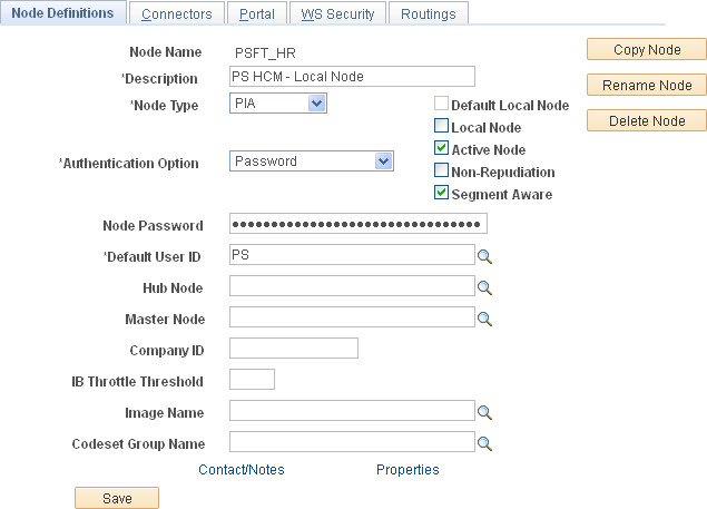
Select the Node Definitions page:
Enter a description for the remote node.
Verify that the node type is PIA.
For default local nodes only, set the authentication option to Password or Certificate. If the authentication type is password, enter the password defined for the remote node.
Enter the default user ID as defined on the remote node.
Important! If necessary, add a user profile for this default user ID.
This example illustrates the fields and controls on the Node Definitions page showing a remote default local node.
See the product documentation for PeopleTools: Integration Broker Administration, “Setting Up Secure Integration Environments,” Implementing Node Authentication, PeopleTools: Integration Broker Administration, “Adding and Configuring Nodes,” Defining Node Parameters.
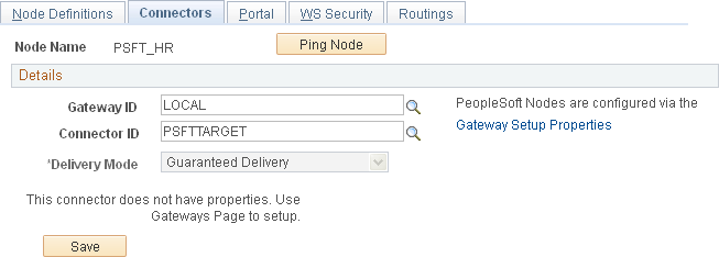
Select the Connectors page:
Enter the integration gateway in the Gateway ID field. If the remote node will use the locally defined integration gateway, enter LOCAL as the gateway ID.
Enter PSFTTARGET as the connector ID.
This example illustrates the fields and controls on the Connectors page showing a remote default local node.
See the product documentation for PeopleTools: Integration Broker Administration, “Adding and Configuring Nodes,” Specifying Gateways and Connectors.
For default local nodes only, if the remote node will use the locally defined integration gateway and you did not add this node to the gateway configuration previously, do so now.
Click the Gateway Setup Properties link to add the remote node to the integration gateway.
See Configuring the Integration Gateway.
After the remote node has been added to the integration gateway, click the OK button to return to the Connectors page.
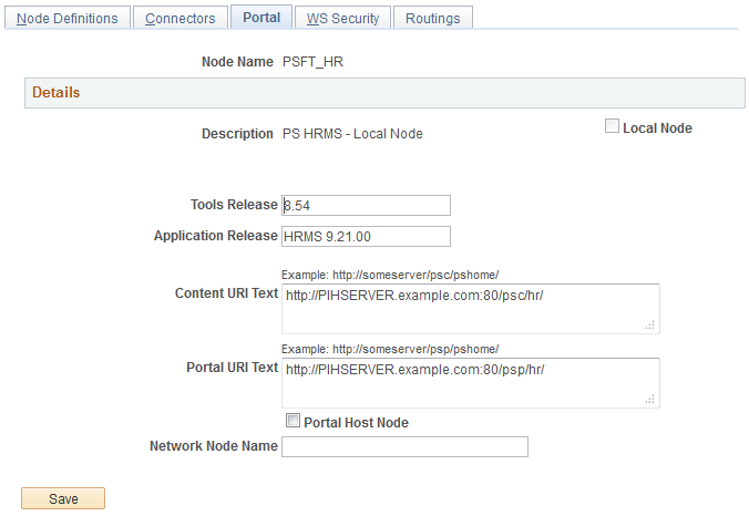
Select the Portal page:
Ensure that a value is defined for the Tools Release field.
Enter values for the Content URI Text field and the Portal URI Text field as defined for the remote node.
Ensure that the Portal Host Node check box and the Network Node Name field are set on the portal system and on a participating (remote) system. These fields are set so that the unified landing page is able to obtain the corresponding IB node for a given portal host node.
Select the Portal Host Node check box and enter the default local node of the remote system in the Network Node Name field.This example illustrates the Portal page showing a remote default local node.
See the product documentation for PeopleTools: Portal Technology, “Configuring the Portal Environment,” Setting Portal Nodes.
Save the definition of the remote node.
Repeat steps 2 through 6 for each default local node and portal host node that needs to be defined as a remote node in the portal system.
Defining Remote Nodes on a Content Provider System
To define remote nodes on a content provider system:
Select
If the default local node for the portal system (PSFT_PA) is already defined in the content provider database, then select that node definition. Otherwise, add a new value for PSFT_PA.
Select the Node Definitions page:
Enter a description for the remote node.
Verify that the node type is PIA and that the Authentication Option field value is Password or Certificate. If the authentication type is password, enter the password defined for the remote node.
Enter the default user ID as defined on the remote node.
Important! If necessary, add a user profile for this default user ID.
See the product documentation for PeopleTools: Integration Broker Administration, “Setting Up Secure Integration Environments,” Implementing Node Authentication, PeopleTools: Integration Broker Administration, “Adding and Configuring Nodes,” Defining Node Parameters.
Select the Connectors page:
Enter the integration gateway in the Gateway ID field. If the remote node will use the locally defined integration gateway, enter LOCAL as the gateway ID.
Enter PSFTTARGET as the connector ID.
See the product documentation for PeopleTools: Integration Broker Administration, “Adding and Configuring Nodes,” Specifying Gateways and Connectors.
For default local nodes only, ithe remote node will use the locally defined integration gateway, click the Gateway Setup Properties link.
Log in on the Gateway Properties page.
Enter the default local node in the PeopleSoft Nodes group box:
Click the Save button.
Click the Ping Node button for the remote node that is the default local node.
Note: A central gateway should be used by all databases in the same portal cluster.
The status should return as success.
Note: If you click the Ping Node button for a remote node that is a portal host node, the following error will result:
Integration Broker Service:
Destination node does not match the local  node. (158,506)
On the Ping Node Results page, click the Return button.
Click the OK button to return to the Connectors page.
Select the Portal page:
Enter values for the Content URI Text field and the Portal URI Text field as defined for the remote node.
Ensure that a value is defined for the Tools Release field.
Ensure that the Portal Host Node check box and the Network Node Name field are set on the content provider system. These fields are set so that the unified landing page is able to obtain the corresponding IB node for a given portal host node.
For each of the local nodes, select the Portal Host Node check box and enter the default local node of the portal system in the Network Node Name field.See the product documentation for PeopleTools: Portal Technology, “Configuring the Portal Environment,” Setting Portal Nodes.
Save the definition of the remote node.
Repeat steps 1 through 5 for each portal host node (EMPL, CUST, PART, SUPP, and ENTP) from the portal system.
Repeat steps 1 through 5 for each default local node and portal host node from the other content provider systems that needs to be defined as a remote node in this content provider database.
Repeat steps 1 through 7 on each content provider system.
After the remote nodes have been defined on each system, all the default local nodes participating in the single signon configuration need to be identified on each system.
Identifying Trusted Nodes on the PeopleSoft Interaction Hub System
To identify the trusted nodes on the portal system:
Select to open the Unified Navigation WorkCenter page.
In the Unified Navigation pagelet, expand the Single Signon Setup section and select the Define Trusted Nodes link to open the Single Signon page in the target area.
Alternatively, select
This example illustrates the Single Signon page listing all trusted default local nodes.
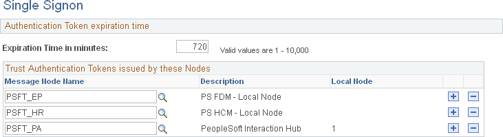
See the product documentation for PeopleTools: Security Administration, “Implementing Single Signon,” Implementing PeopleSoft-Only Single Signon, Working with the Single Signon Page.
Add the default local node from each content provider system as a trusted node.
Save the list of trusted nodes.
Identifying Trusted Nodes on a Content Provider System
To identify the trusted nodes on a content provider system:
Select
See the product documentation for PeopleTools: Security Administration, “Implementing Single Signon,” Implementing PeopleSoft-Only Single Signon, Working with the Single Signon Page.
Add the default local node (PSFT_PA) from the portal system as a trusted node.
If single signon is also to be implemented between content provider systems, then add the default local node from each content provider system as a trusted node.
Save the list of trusted nodes.
Repeat steps 1 through 4 on each content provider system.
Once content provider nodes have been defined in the portal system, only default local nodes need to be added to the integration network to complete the network configuration.
Note: If you added default local nodes from the content provider systems to the integration network previously, then you might not need to complete this procedure.
See Configuring the Integration Gateway.
To add default local nodes from the content provider systems to the integration network:
Select to open the Unified Navigation WorkCenter page.
In the Unified Navigation pagelet, select the IB Network WorkCenter link to open the integration network's Configuration Status page.
Click the Node Network Configured link.
Alternatively, select
See the product documentation for PeopleTools: Integration Broker Administration, “Using the Integration Network,” Viewing Node Network Status.
For each remote node that is a default local node, select the option to make the node in network.
This example illustrates the Node Network page showing the portal’s default local node (PSFT_PA) and one remote default local node (PSFT_HR) as in-network.
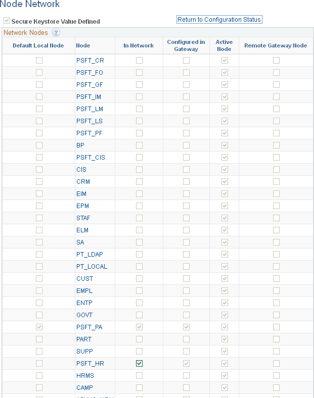
Save the changes to the integration network.
You can test your single signon configuration from the portal system after the remote nodes have been defined and added to the integration network. The Unified Navigation Node Network page includes a button that allows you to test single signon for each remote node that has been defined as part of the integration network.
In addition, successfully testing single signon requires that you complete the initial configuration steps.