Configuring the Integration Gateway
To configure the Integration Broker integration gateway and start the setup of the integration network on your portal system:
Select to open the Unified Navigation WorkCenter page.
In the Unified Navigation pagelet, select the IB Network WorkCenter link to open the integration network's Configuration Status page.
Alternatively, select
This example illustrates the Configuration Status page showing that the Integration Network is not configured.
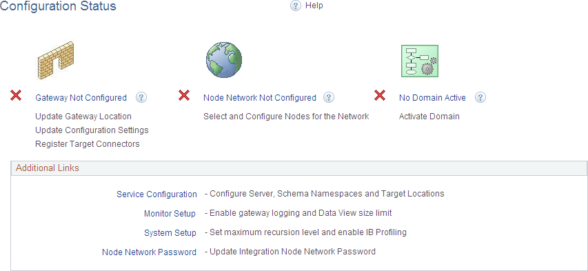
See the product documentation for PeopleTools: Integration Broker Administration, “Using the Integration Network,” Using the Configuration Status Page.
Click the Gateway Not Configured link.
The Gateways page appears.
See the product documentation for PeopleTools: Integration Broker Administration, “Using the Integration Network,” Verifying and Managing Integration Gateway Configuration.
Configure the integration gateway:
Enter the machine name and complete URL to the PeopleSoftListeningConnector in the Gateway URL field:
This example illustrates the fields and controls on the Gateways page with a gateway URL configured.
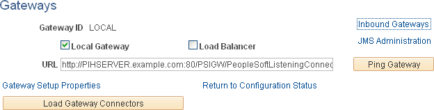
Click the Ping Gateway button.
The status should return as active.
Click the Load Gateway Connectors button to load the gateway connectors.
This example illustrates the fields and controls on the Gateways page with connectors loaded.
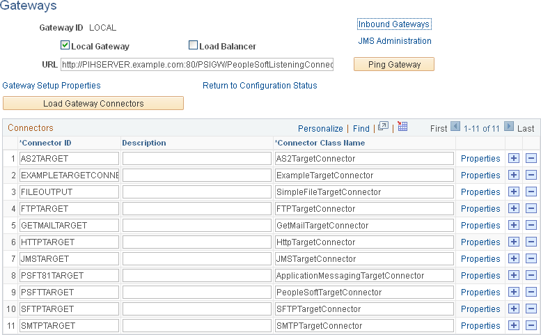
Click the Save button to save your changes.
Click the Gateway Setup Properties link.
Log in on the Gateway Properties page.
The PeopleSoft Node Configuration page appears.
See the product documentation for PeopleTools: Integration Broker Administration, “Managing Integration Gateways,” Setting Oracle Jolt Connection Properties.
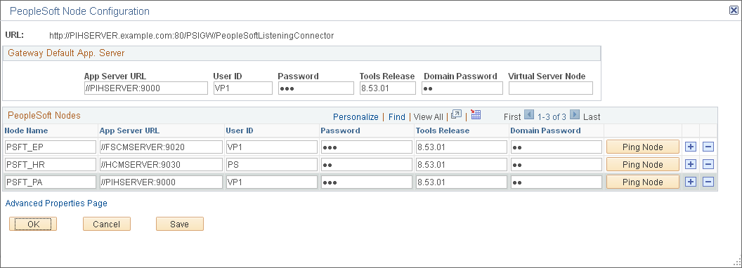
Enter the URL to the gateway and other values in the Gateway Default App. Server group box.
At a minimum, enter the values for the default local node in the PeopleSoft Nodes group box.
This example illustrates the fields and controls on the PeopleSoft Node Configuration page.
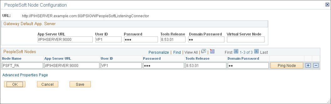
Click the Save button.
Click the Ping Node button.
The status should return as success.
On the Ping Node Results page, click the Return button.
If you have the information now, you can define other participating nodes in the PeopleSoft Nodes group box at this time. For each content provider system, create entries for the default local node.
This example illustrates the PeopleSoft Node Configuration page with a shared gateway configured.
Note: Alternatively, you can return to this PeopleSoft Node Configuration page once you have identified and defined these nodes.
Save your changes.
Then, for each default local node defined, click the Ping Node button.
The status might not return success if the node is not yet defined with the same parameters in both systems.
Note: If you click the Ping Node button for a any node that is a portal host node, the following error will result:
Integration Broker Service:
Destination node does not match the local  node. (158,506)
On the PeopleSoft Node Configuration page, click the Advanced Properties Page link.
The Gateway Properties page appears.
See the product documentation for PeopleTools: Integration Broker Administration, “Managing Integration Gateways,” Using the integrationGateway.properties File.
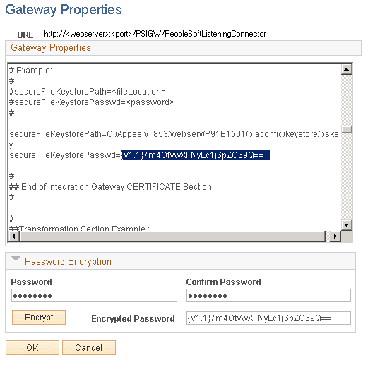
Enter the full path to the keystore file and enter the encrypted keystore password:
This example illustrates the fields and controls on the Gateway Properties page.
See the product documentation for PeopleTools: Integration Broker Administration, “Managing Integration Gateways,” Configuring Security and General Properties, PeopleTools: Integration Broker Administration, “Managing Integration Gateways,” Encrypting Passwords.
Click the OK button.
On the PeopleSoft Node Configuration page, click the Save button again.
Click the OK button.
On the Gateways page, click the Return to Configuration Status link.
Click the Node Network Not Configured link (or the Node Network Configured link if that is displayed instead).
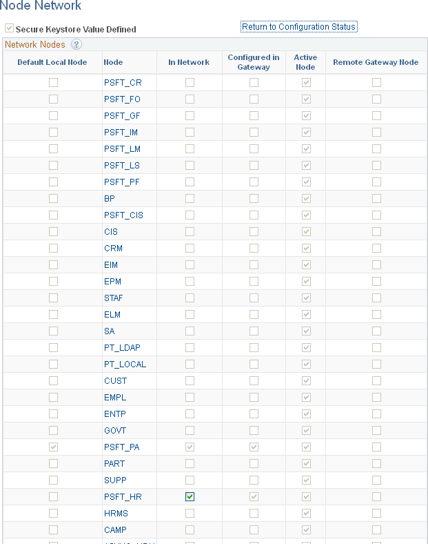
Ensure that the portal system's default local node is selected as in network (it is selected by default).
This example illustrates the Node Network page showing the portal’s default local node (PSFT_PA) and one remote default local node (PSFT_HR) as in-network.
Click Save, then click the Return to Configuration Status link.
Click the No Domain Active link.
The Domain Status page appears.
This example illustrates the Domain Status page with an activated domain.
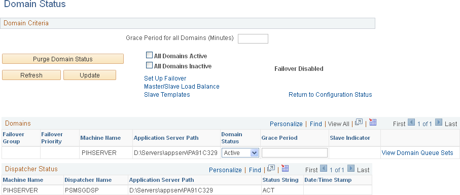
In the Domains group box, set the status for this machine to Active.
Click the Update button to update the domain status.
Return to the Configuration Status page (click the Return to Configuration Status link).
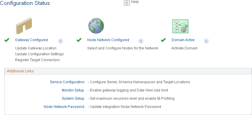
The status should show that all three steps have been completed and that your integration gateway and integration network are configured.
This example illustrates the Configuration Status page showing a configured integration network.
Important! While this integration network is active, its configuration might not yet be complete if you have not added all remote nodes to the integration gateway.