
 Getting Started with Compound Models
This chapter discusses how to:
Get started with compound models.
Create a new compound model project.
Create a configurable component.
Delete a configurable component.
Rearrange components in the compound model.
Add and remove a component model from the project.
Edit default values.
Create and delete relationships between configurable components.
Display a compound model relationship.
Specify required relationships.
Edit component model versions.
Compiling, running, and testing a model.
Team modeling.
Getting Started with Compound Models
The recommended steps for creating a compound model are:
Create the component models that represent the configurable parts of the product. Compile and test them.
Create a new compound model in the Visual Modeler workspace, either a new workspace or an existing one (set it as the active project).
Insert the configurable components that represent the jump-off points for the separate configurations, and associate each with a component model.
Create the relationships between the configurable components.
Set the required relationships for each configuration component.
Create any defaults for the initial instance of each configuration component.
Specify project settings (server name and port).
Compile the project and run it on test JavaServer Pages (compound models do not have a Model Tester as component models do).
When you launch a Compound Model, the Visual Modeler displays the Compound Model Canvas, a UML-style layout grid for constructing and displaying the Compound Model.
|
|
Adds a component to the current project. |
Creating a Compound Modeling ProjectYou can create a new project from the base project template or modify an existing project.
To create a new project from the base project template:
Select File, New to display the New dialog, then click on the Projects tab.
Specify a project name, storage location, and whether to add the project to a current or new workspace. When you click OK, a template project tree appears in the Components tab.
Add models and files to the project as needed.
When you need to build a new compound model from an existing one, you can import its structure, relationships, and defaults from its .xml file.
To create a project from an existing one:
Create a new compound model Project.
Select Project, Import Existing Schema. A browse dialog appears.
Locate and select the appropriate .XML file. The imported structure appears in the Components Tab view with the Compound Model canvas.
Editing Project SettingsProperties associated with the compound model are located in the Compound Model Settings dialog.
|
Compound model version containing two levels, major and minor, used for model maintenance. It is not to be confused with component model versions. |
|
Server: The server on which WebLogic and the Configurator are installed. Port: The port number for the WebLogic application server. Default is 7777. |
Creating a Configurable ComponentA configurable component is based on a existing component model. Thus, you must create and test each component model before proceeding with this step.
See Product Modeling with a Component Model.
Use the component editor to create a configurable component:
|
Name |
Identifies the Configurable component whose instance is being acted upon. The name cannot include \, =, <. >, :, ", (, or ). The initial character cannot be dollar ($) or underscore (_), but these characters can be included in other positions. An asterisk (*) cannot be used alone, but it can be used in combination with other characters |
|
Name of the component model to associate the component to. This model must contain the decision point(s) required by the configurable component. Each configurable component references one model. (However, one model can reference more than one configurable component.) |
|
|
The component can be based on a ConfigurableComponentType. The type definition will be used for any data values not specified within the element definition. Specify either reference or type, but not both. Can be absent. Note. If there is a component model associated with the referenced component, it will be overridden by the component model specified for this component. |
|
|
The component can be based on another configurable component. The referenced component will be used for any data values not specified within the element definition. Either reference or type can be specified, never both. Can be absent. Can be absent. Note. If there is a component model associated with the referenced component, it will be overridden by the component model specified for this component. |
|
|
Version of model to use when a stored configuration is requested by an end user.
|
|
|
A non-negative integer or the term unbounded. Specifies the maximum number of instances that can be created from the component in a single configuration of the compound model. For example, for a telecommunications product being configured for a moderate-sized business customer, the number of OfficePhones is limited by the number of office setups ordered. You can limit the number of phones the end-user can configure by specifying that the Max Occurs value be taken from the OfficeSetup quantity. Note. PeopleSoft Advanced Configurator does not automatically create components or limit deletion of components based on this number—but it will report that the configuration is invalid if the limit is not met.
|
|
|
A non-negative integer. Specifies the minimum number of instances that must be created in order to satisfy the requirements of the product model. For instance, if the end-user creates an configurable instance of an OfficeSetup, they must also configure at least one OfficePhone for that OfficeSetup. The value of Min Occurs would be 1. A value of 0 would indicate that an OfficePhone is optional. Note. Advanced Configurator does not automatically create components or limit deletion of components based on this number – but it will report that the configuration is invalid if the limit is not met.
|
|
|
Any relationship that must be satisfied for the component in order for the configuration to be valid. Important: Important! This property does not actually implement the relationship; that must be done by the web application developer. It does, however, verify that such a relationship is satisfied. Setting required relationships for the component here sets up a validation function that, when violated (the end-user has not added a necessary component, for instance), an error message is generated for the end-user. See Creating and Deleting Relationships Between Configurable Components. |
Note. “Inherit” check boxes appear when the configurable component has a type or reference specified.
Repeat these steps for each configurable component desired.
To create a configurable component:
Make sure that the Compound Model Canvas is displayed, and that the desired project is selected (if the workspace contains more than one project).
Do one of the following:
Click the icon at the taskbar on the right of the window.
Or,
Choose Insert, Configurable Component.
Move the cursor onto the blue grid where you want the configurable component to appear in the model structure.
Click once to create the component. You can drag-and-drop to reposition it.
Double-click on the component to display its component editor
Enter the appropriate values for the elements. Values for Type, Defaults, and Required Relationships may not be available, as they must be created separately. These can be added later.
Repeat these steps for each configurable component desired.
Deleting a Configurable ComponentTo delete a configurable component in the Compound Model canvas, right-click on the desired component and select Delete “<component name>”.
To delete a configurable component in the Components Tab view, right-click on the desired component and select Delete from the menu.
Rearranging Components in the Compound ModelWhenever you are using the Compound Model Canvas to create and link components, you can use the View, Relayout Canvas command to efficiently reposition the components in the window.
Adding and Removing a Component Model from the ProjectAdding a component model adds a component model to the project. Once added, the model name makes it available for connection, via various selection lists, to other component models. Adding a model to the project does not connect it in the compound model. This is done when you create configurable components.
|
|
Launches the Model Manager dialog |
To add a component model:
Do one of the following to display the Model Manager:
Select View, Model Manager.
Or,
Click the Model Manager icon in the tool palette.
In the Model Manager dialog, click the New button to open the New Configurator Model Link dialog.
Type the model name in the name field, for example, ConfRoom, or Hub. (The Configurator looks for models at the specified Configurator server location.)
Set the Version preferences and click OK.
Default for each version level is Use Latest, which means the latest version of the model found in the model directory will be used for compiling. You can instead specify a specific model version down to the micro level, or you can specify only certain levels. To specify the version number, click the check box to clear the check and enable the version selector.
Examples:
|
For any version 1.2.1 – 1.2.10, |
|
|
If you specify |
Configurator uses |
|
1-2-5 |
1.2.5 |
|
1-2 |
1.2.10 (the latest) |
|
1 |
1.2.10 (the latest) |
|
For any version 1.1.0 – .1.59, |
|
|
If you specify |
Configurator uses |
|
1–1 |
1.1.59 (the latest) |
Removing a component model is more accurately described as removing the link to the component model that exists in the compound model.
Note. Removing a component model from the compound model is not the same operation as deleting a configurable component.
To remove a component model:
Do one of the following to display the Model Manager:
Select View, Model Manager.
Or,
Click the Model Manager icon in the tool palette.
In the Model Manager, select the component model that you want to remove from the compound model and click the Delete button.
You will be notified if there are any components that are dependent on the one being removed. Note the dependencies and click OK to the message. You will need to make provision for the removed component model.
Click OK to close the dialog. The component will be removed from component windows during the next compile.
Editing Default ValuesDefaults are the values that appear on instances of configurable components when they are created from the component models of a compound model. By definition, they are the same as defaults for a component model. But because the initial instance is created within the context of the compound model, with potential dependencies on other component models, their defaults may not be the same as they would be if an instance was created from the model in its standalone state.
Defaults are listed with Configurable Components and Relationships in the Components View tab.
|
Attribute Name—The name of the attribute in a component model to which to assign the Attribute Value. Attribute Value—The value you wish the attribute to have when the configurable component is initialized. Leave these blank if you do not need attribute defaults. |
|
|
A specific value. A domain member of a particular selection point within the associated component model. If applicable, enter a quantity of the item. You can leave this value blank. Use this value when you have a specific selection point in a specific component model to specify. |
|
|
A value provided by a source outside the component model that is only known at run time, such as user-entered text, numbers, boolean values, and dates, . In the component model, this will be an extern. Leave these blank if you do not need attribute defaults. |
|
|
|
Opens the Defaults window for new defaults specifications. |
|
|
Adds rows to the table so that you can edit additional attributes, choices, and external choices. |
|
|
On the External Choice element, adds rows so that you can add additional Values to the parent Selection Point. |
|
|
Deletes the selected row. |
To specify or edit default values:
For a new default, open a new Default window in one of three ways:
To change an existing default double-click its name in the Components View tab.
Double-click on Defaults in the Components tab.
From the Configurable Components window, select Insert, Defaults.
Click the Defaults icon in the tools palette
Specify or edit the desired defaults.
In each of the tables in the Default window, use the Add button to add a new attribute, choice, or external choice default.
Creating and Deleting Relationships Between Configurable ComponentsRelationships in a compound model define interactions between components (component models). By contrast, relationships within component models define interaction between classes and domain members.
|
Name of the component model to which data is to be passed. |
|
|
Component—the component that can be connected to the target component. Click on the field to activate the drop down list. There can be more than one. Use the Add (+) button to add more components. This relationship property establishes the structure of the compound model and is the basis for Required Relationship validations. Default is none. See Modeling Strategy. Min Occurs—The minimum number of components (instances) that must be connected to the target component for the configuration to be valid.
Max Occurs—The maximum number of components that can be connected to the target component in the configuration. Default value is unbounded. A value of 0 is meaningless. A value of 1 to 99 indicates the upper limit of allowable connections of this component to the target component. Unbounded indicates that there is no limit to the number of this component’s connections to the target. |
|
|
|
Adds a new connection point. |
|
|
Opens the properties dialog for the connected component displayed. Located above the Connection Point Table. |
|
|
Opens the Relationship editor. Located on the Tools taskbar at the right of the window. |
|
|
Adds a row (connection point instance) to the Connection Point table. |
To create a compound model relationship:
Do one of the following:
—From the main menu, choose Insert, Relationship.
Or,
—From the Tools taskbar at the right of the window, click the Relationship icon.
The Relationship Editor appears.
Enter the appropriate values.
To add or view the properties of the connected components, click on the Properties button above the Connection Point Table.
Set the Connection Point information. A Connection Point is a data element that is to be passed along the connection represented by the relationship. There can be 0, 1, or more than 1 Connection Points.
Click the Add button to add a new Connection Point.
Enter Connection Point values.
|
If you want to assign a Connection Point type, click on the field to activate the drop down for selection. Depending on the type you choose, the operation and source or Target properties will be provided and will appear in italics (italics indicate properties inherited from types). If you don’t want to assign a Connection Point type, leave the default value of None and assign the values Operation and either Source or Target. |
|
|
Describes the origin of the data to gather. It can be: Choice—Indicates the data is a value from a particular selection point domain member or attribute. If Choice is selected, you must provide the Target selection point in the Connect Components table (following). Target Variable and Numeric Data do not apply to Choice operations. Collection—Indicates the data is a set of values taken from all the sources that have a particular attribute in common. If you choose the Collection operation, you also must specify Target Variable and Numeric Data (following). None—Default value; used when an inherited value will provide the value. |
|
|
Identifies the selection point that provides the data to be communicated over the connection. You may need to open the component model with Visual Modeler (in another window is easier) to obtain the correct name of the selection point. |
|
|
The name of the object in which to store the collected values of a Collection operation. Not required for Choice operations. This information is located in the component model that is to receive the information (connected component). |
Configure the instance(s) of the Connection Point by first expanding the row with the Add Instance button.
If there is only the header for the instance row as in the image above, click the button to add an instance.
If the Connection Point has a type, an instance will already be created and any inherited properties will be entered in the fields. If not, enter these values:
|
Specifies how the instances of the Connection Point are to handle the data received. Entries are All, 0, 1, 2, .... n. All indicates that all instances of the Connection Point handle the data as specified in the Target DP or Numeric Data columns. 1....n indicates order of creation of the instances of the Connection Point at run time. |
|
|
If the Operation is Choice, you must specify which selection point (DP) in the source is to receive the data. In this example, the first instance of Ext_voicemailLimitSet will receive the data from the Source DP. |
|
|
If the Operation is Collection, you must specify the name of the variable that will contain the data. Because this is a set of numerals, it is called Numeric Data. In this example, all instances of the Source DP will contribute data, which, once all data is collected, will be sent to the object lines. |
If there are additional Targets to receive source data, click the Add Instance button again to add another row.
To add or view documentation about the values, click on the Properties button above the Connection Point Table.
Click OK to create the new Connection Point.
For the example below, the first instance of <ConnectionPt>_CP1, Instance 1, will send the data to a Target DP called LineA. Instance 2, however, sends its data to LineB; Instance All represents data from both LineA and LineB that the component model sums, placing the result in Target DP LineSum.
Displaying a Compound Model RelationshipTo open a previously unopened Relationship Editor window, double-click on the desired relationship in the Components tab.
If the relationship is already displayed but is not the active window, click on its tab. Relationship windows are indicated by the Relationships icons:
Specifying Required RelationshipsRequired relationships are those that must be satisfied before a configuration is considered valid. Your product’s business logic determines what relationships are required. For example, a telecom service product includes a limit on the number of voicemail accounts on certain phones. The limit applies to phones to be installed in conference rooms and offices. The components ConferenceRoom and Office can then be said to be connected to the target component OfficePhone with a voicemail limit relationship (VML):
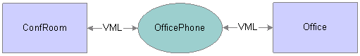
The required relationship VML must connect OfficePhone with ConfRoom or Office
This relationship is represented in the Visual Modeler in the Relationship editor as illustrated below:
When a ConferenceRoom is not connected to an OfficePhone (perhaps another phone model is desired), the relationship does not apply. To indicate that the OfficePhoneVMailLimit is required, you must specify it in the target component’s properties editor as described in this section.
|
|
Displays a list of relations for the project. |
|
|
Click the Add All Of button to insert a blank All Of clause in the Required Relationships panel at the location of the selected clause or relationship name. |
|
|
Click the Add Any Of button to insert a blank Any Of clause in the Required Relationships panel at the location of the selected clause or relationship name. |
|
|
Click the Add Exactly One Of button to insert a blank Exactly One Of clause in the Required Relationships panel at the location of the selected clause or relationship name. |
Editing Component Model VersionsAt run time, a compound model communicates with component models (its designated component models), which are located separately. The compound model contains only a link to its component models. Since component models are independently built and maintained, provision for version specification is included in the Compound Model.
Component model versions are specified in the Model Manager dialog. Default version is 1-0-0 (Major-Minor-Subminor).
The figure shows the version of the component model ConfRoom is specified to the Minor level; the Micro level is always the latest. So, at run time, the model accessed will be ConfRoom version 1-7-<latest available>.
To edit a component model version:
Do one of the following to access the Model Manager: Select View, Model Manager. Or, Click the Model Manager icon in the tool palette. The Model Manager appears. Note the version settings for each model.
Select the desired component model and click the Edit button.
Designate the desired level or check the “Use Latest” check box. Click OK.
Default for each version level is “Use Latest,” which means that the latest version of the model found in the model directory will be used for compiling. You can instead specify a specific model version down to the sub-minor level, or you can specify only certain levels. To specify the version number, click the check box to clear the check and enable the version selector.
Compiling, Running, and Testing a Compound ModelA Compound model must be tested on test JSP pages since there is no Model Tester as there is for a component model.
To test a Compound model:
Compile and run each component model separately in component model mode. Make sure that each runs to your satisfaction.
Select Project, Compile Only to compile the Compound model. The compound structure definition document (.XML) will be created and placed on the server specified in the compound model settings. You can also launch the Configurator Administration Tool (from the Start/Program menu) to view the .XML file.
Create JSP pages appropriate to test the connections and constraints between the component models. JSP pages for the sample compound model are available for modification.
Use the JSP pages to create a test web application and deploy it in a test environment.
Warning! Make sure that your browser is cookie-enabled; compound models require the use of cookies to function properly at run time.
Team ModelingNot only does Visual Modeler permit simultaneous development of the files of a single model, but team members can work on the different component models simultaneously. Updating a compound model with new versions of component models is managed in the Model Manager, which allows modelers to specify the model version to include in the compound model at compile time. Modelers can specify stable versions of the component models against which to test their updated model, thus controlling their test environment.