Configuring Routing Definitions
This section discusses how to:
Define general routing information.
Define routing parameters.
Define and override gateway and connector properties.
Define routing properties.
After you add a routing definition to the system use the pages of the Routing component to define the routing details. Use the Routings – Routing Definitions page to define general routing information.
This example illustrates the fields and controls on the Routings – Routing Definitions page when you are working with a synchronous service operation. You can find definitions for the fields and controls later on this page.
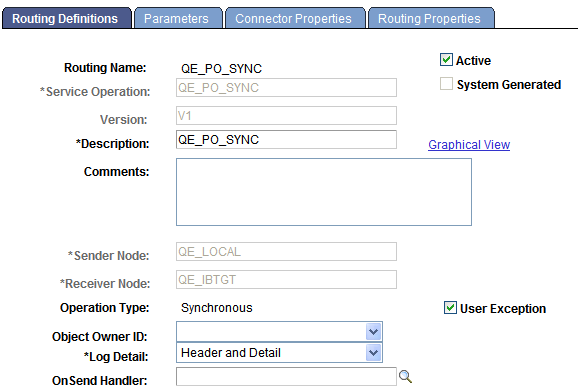
The fields that appear on the Routing–Routing Definitions page vary based on if you are defining a routing for a synchronous service operation or an asynchronous service operations.
The various ways to access this page are discussed in the previous section.
See Understanding Adding Routing Definitions.
When you add a routing definition from a service operation record, the PeopleSoft system automatically populates some of the data on this page based on the data in the service operations record from which you created the routing. Automatically populated data includes the service operation name, version, and routing type.
Field or Control |
Description |
|---|---|
Routing Name |
Indicates the name of the routing definition. This name is specified when you add a routing definition to the system. |
Service Operation |
Enter the name of the service operation that will use the routing. If you access the Routings component from the Service Operations – Routings tab, PeopleSoft Integration Broker automatically populates this information. |
Active |
(Optional.) Select the check box to activate the routing. By default, new routing definition are active. If any of the referenced nodes are inactive, you cannot activate the routing. |
System Generated |
When selected, indicates that the PeopleSoft system generated the routing definition. |
Version |
Indicates the version of the service operation selected. |
Description |
Description of the routing definition. If you do not enter a description, this value defaults to the name of the service operation associated with the routing definition upon save. |
Graphical View |
Click this link to view saved routing definitions in graphical format. |
Comments |
(Optional.) Enter comments about the routing definition. |
Sender Node |
Enter the name of the sending node. |
Receiving Node |
Enter the name of the receiving node. |
Unordered Segments |
(Optional.) Select the check box to indicate that system should process the service operation messages in parallel. The Unordered Segments check box appears only under the following conditions:
This feature is frequently used in conjunction with the OnPreNotify Handler and OnPostNotify Handler fields to perform pre- or post-processing on segmented messages. |
Operation Type |
Indicates the service operation type. PeopleSoft Integration Broker automatically populates this information when you select the service operation. |
User Exception |
The User Exception check box displays only for synchronous service operations. (Optional.) Select the check box to enable exception handling using PeopleCode. When enabled and an error occurs you can handle any errors in the calling PeopleCode. If not enabled any errors that occur cause the program to stop. |
Object Owner ID |
(Optional.) From the drop-down list box, select the owner of the definition. The owner ID helps to determine the application team that last made a change to the definition. The values in the drop-down list box are translate table values that you can define in the OBJECTOWNERID field record. |
OnPreNotify Handler |
(Optional.) From the drop-down list box, select an OnPreNotify handler to perform pre-processing on segmented messages being processed in parallel by the system. This page control appears only when the Unordered Segments check box is selected. |
OnPostNotify Handler |
(Optional.) From the drop-down list box, select an OnPostNotify handler to perform post-processing on segmented messages being processed in parallel by the system. This page control appears only when the Unordered Segments check box is selected. |
Accept Compression |
(Optional.) The Accept Compression check box displays only for inbound synchronous non-REST service operations. Setting compression for REST service operations is discussed elsewhere in the product documentation. See Setting Compression for REST Service Operations. Select the check box for the system to send the response to the consumer compressed. You must compress the response before sending, using PeopleCode or by setting the Min Message Size Compression parameter in PSAdmin. You can override the compression of the response using PeopleCode by setting the CompressionOverride property on IBInfo. The following example shows sample PeopleCode to override compression of the response message: |
Log Detail |
The Log Detail drop-down list box displays only for synchronous service operations. This option enables you to set the level of information logging for synchronous messages that is viewable in the Service Operations Monitor. The valid values are:
|
Service Operation Security |
A Service Operation Security link appears when the selected routing definition is for an outbound REST-based service operation Click the link to access the Web Service Access page and to add permissions to the view details for the service operation in the Service Operations Monitor. |
OnSend Handler |
This field displays when an OnSend handler is defined for the service operation and the sending node is the local node. It also displays when the system is serving as a hub, and neither the sender nor receiver are local. Select a handler from the list. This handler runs when a message is sent or received to perform processing logic. |
Schema Validation Details |
This field displays only when working with any-to-local routing definitions. (Optional.) When this check box is selected and a schema validation error occurs the raw schema parser errors are returned to the consumer within the default message CDATA tag. If the check box is not selected (Default) then if a schema validation error occurs the systems uses the standard message set/ ID framework to generate the error. |
OnReceive Handler |
This field displays when an OnReceive handler is defined for the service operation and one of the following conditions exists:
Select a handler from the list. This handler runs when a message is sent or received to perform processing logic. |
Use Secure Target Location |
This check box appears only when you are working with an outbound asynchronous request/response service operation. Select the check box to use the secure target location as the endpoint for the response. If the check box is not selected, the (unsecured) target location is used. |
This section provides an overview of defining transformations for any-to-local routing definitions and discusses how to define general routing parameters.
Understanding Routing Parameters for Requests and Responses
A routing definition contains routing parameters for each inbound request, inbound response, outbound request and outbound response associated with a service operation. The routing parameters that you can define include for each request or response include, routing alias, message names before and after transformation, and transformation program names.
You define routing parameters using the Routings – Parameters page in the Routings component.
The following tables list the number of routing parameters a routing definition contains based on the service operation type and whether the sending and receiving nodes are local.
Note: Parameters for routing definitions for REST service operations are not included in the following tables, since they are system generated.
Asynchronous service operations have the following routing parameters:
|
Service Operation Type |
Sender is Local |
Receiver is Local |
Inbound Request Routing |
Outbound Request Routing |
Inbound Response Routing |
Outbound Response Routing |
|---|---|---|---|---|---|---|
|
Asynchronous One- Way |
Y |
Y |
N |
Y |
N |
N |
|
Asynchronous One- Way |
Y |
N |
N |
Y |
N |
N |
|
Asynchronous One- Way |
N |
Y |
Y |
N |
N |
N |
|
Asynchronous One- Way |
N |
N |
Y |
Y |
N |
N |
Synchronous service operations have the following routing parameters:
|
Service Operation Type |
Sender is Local |
Receiver is Local |
Inbound Request Routing |
Outbound Request Routing |
Inbound Response Routing |
Outbound Response Routing |
|---|---|---|---|---|---|---|
|
Synchronous |
Y |
Y |
Y |
Y |
Y |
Y |
|
Synchronous |
Y |
N |
N |
Y |
Y |
N |
|
Synchronous |
N |
Y |
Y |
N |
N |
Y |
|
Synchronous |
N |
N |
Y |
Y |
Y |
Y |
Asynchronous-to-synchronous service operations may have the following routing parameters:
|
Service Operation Type |
Sender is Local |
Receiver is Local |
Inbound Request Routing |
Outbound Request Routing |
Inbound Response Routing |
Outbound Response Routing |
|---|---|---|---|---|---|---|
|
Asynchronous-to-synchronous |
Y |
Y |
Y |
N |
N |
Y |
|
Asynchronous-to-synchronous |
Y |
N |
N |
Y |
Y |
N |
|
Asynchronous-to-synchronous |
N |
Y |
Y |
N |
N |
Y |
|
Asynchronous-to-synchronous |
N |
N |
Y |
Y |
Y |
Y |
Asynchronous request/response service operations may have the following routing parameters:
|
Service Operation Type |
Sender is Local |
Receiver is Local |
Inbound Request Routing |
Outbound Request Routing |
Inbound Response Routing |
Outbound Response Routing |
|---|---|---|---|---|---|---|
|
Asynchronous Request / Response |
Y |
Y |
N |
Y |
Y |
N |
|
Asynchronous Request / Response |
Y |
N |
N |
Y |
Y |
N |
|
Asynchronous Request / Response |
N |
Y |
Y |
N |
N |
Y |
|
Asynchronous Request / Response |
N |
N |
Y |
Y |
Y |
Y |
Understanding Transformations on Any-to-Local Routing Definitions
If you define a transformation on an any-to-local routing definition, the system uses the input message.version on the transform for the inbound request for WSDL. If a transform is defined on the outbound response, then the system uses the message.version on the output of the transformation for WSDL.
In cases where the input message.version or output message.version are not defined on the transform, the system uses the request or response message.version defined on the service operation for WSDL.
Note that any-to-local routing definitions are read-only when WSDL has been exported. As a result, you cannot change the in/out message transformation, aliases, and so on.
Defining Routing Parameters for Requests and Responses
Use the Routings-Parameters page (IB_ROUTINGDEFNDOC) to view and define parameters for requests and responses associated with a service operation. Information you define includes, routing external aliases for inbound and outbound requests and responses, as well as any inbound or outbound transformations to invoke.
To access the Routings - Parameters page, select and click the Parameters tab.
This example illustrates the fields and controls on the Routings – Parameters page. You can find definitions for the fields and controls later on this page.
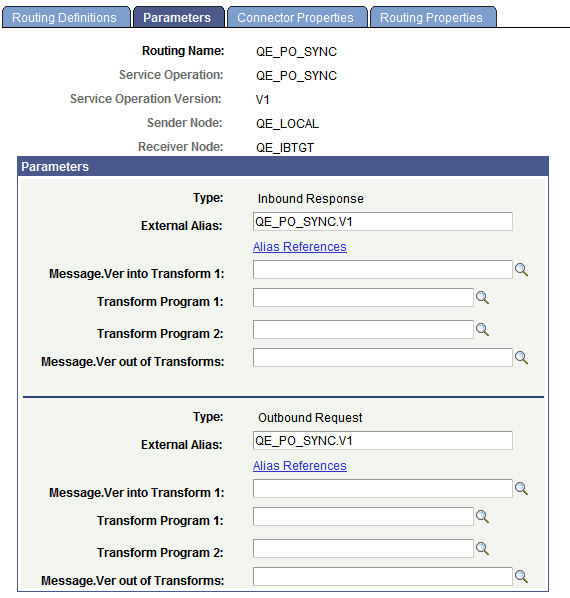
The following page elements display on the Routings-Parameters page:
Field or Control |
Description |
|---|---|
Type |
Specifies the routing direction and the type of message (request or response) associated with the service operation. This information is automatically populated from the service operation definition. |
External Alias |
This alias is used as a SOAPAction attribute in the WSDL binding to identify the service operation in the Integration Broker metadata. The routing external alias defaults to <ServiceOperationAlias>.<Version>, if present. Otherwise it defaults to <ServiceOperation>.<Version>. In an asynchronous request/response any-to-local routing, the outbound routing alias format is <Alias Name>_CALLBACK.<Version>. For inbound transactions you can fire multiple service operations for one invocation when external aliases on the routing definition are the same for each service operation. This is called service operation mapping. See Service Operation Mapping. Duplicate external aliases are not allowed for synchronous operations. |
Alias References |
Click the link to view other routing definitions with the same external alias. |
WS Security |
This link appears on the Parameters page when you are working with:
|
Message.Ver into Transform 1 |
Displays the name of the request or response message associated with the service operation before any transformations are applied. For inbound transactions, this is the message name and version as it arrives from the integration partner system, before any transformations are applied. For outbound transactions, this is the message name and version directly from the PeopleSoft system, before any transformations are applied. |
Transform Program 1 |
(Optional.) Enter the name of the transform program to invoke on the message listed in the Message.Ver into Transform 1 field. |
Transform Program 2 |
(Optional.) Enter the name of the transform program to invoke after the transform program in the Transform Program 1 field has completed processing. When you invoke two transform programs, the output from the first transform program (Transform Program 1) is used as the input into the second transform program (Transform Program 2). |
Message.Ver out of Transforms |
(Optional.) Enter the name of the message after all transform program have completed processing. For inbound messages, this is the message name and version that the PeopleSoft system is expecting. For outbound messages, this is the message name and version that the integration partner system is expecting. |
When the Routings-Parameters page first displays values for the Message.Ver into Transform 1 and Message.Ver out of Transforms fields display values to assist you in choosing transform programs. After you save the page, values do not appear in these fields unless the transform programs have an input/output messages associated with them.
Note: Based on the transform selected, the message.version of the inbound request or response and the message.version of the outbound request or response that the system populated on the page can be different then those specified on the component. Should this occur a warning message displays and you can accept or reject the message.version information populated on the Routings - Parameters page. If you reject the message.version information populated on the page, you can modify the fields with the appropriate message.version information, or change the information that is specified on the component.
The Routings-Connector Properties page (IB_ROUTINGDEFCON) enables you to define and override the default integration gateway and target connector that the local node uses to communicate with an endpoint for a specific routing definition.
To access the Routings – Connector Properties page select and click the Connector Properties tab.
Note: The Routings – Connector Properties page displays in the Routings component only if the receiving node is not the local node.
This example illustrates the fields and controls on the Routings – Connector Properties page. You can find definitions for the fields and controls later on this page.
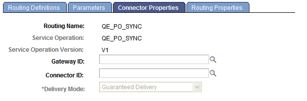
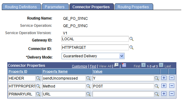
After you select an integration gateway and target connector with which to work, the system displays the required properties for the connector that you can set and override. To set or override additional properties add them to the properties list with the desired values.
This example illustrates the Routings – Connector Properties page. The example shows the properties for the HTTP target connector.
The Routings-Connector Properties tab features the following controls:
Field or Control |
Description |
|---|---|
Gateway ID |
Click the Lookup button to select an integration gateway. |
Connector ID |
Click the Lookup button to select a target connector that resides on the gateway entered in the Gateway ID field. After you select a target connector, its required properties appear. |
Delivery Mode |
Select one of the following options:
These options are discussed in detail elsewhere in the product documentation. |
Save |
Click the Save button to save your changes. |
Overriding Default Integration Gateways
To override the default integration gateway, use the Gateway ID field Lookup button to select a gateway. You must also select a target connector on the new gateway to use and define properties for that connector.
Overriding Default Target Connectors
To override the default target connector on the default integration gateway, use the Gateway ID field Lookup to select the default gateway. Use the Gateway ID field Lookup to select a different target connector that resides on the gateway and then define properties for the new connector.
For REST-based services the connector ID default to HTTPTARGET and cannot be changed.
Overriding Default Connector Properties
To override the default target properties for the default target connector, use the Gateway ID field Lookup button to select the default gateway. Use the Connector ID field Lookup to select the default target connector and then adjust the gateway properties as appropriate.
HTTP header properties, those with the property ID of HEADER, are the only properties you can add for routings for outbound REST-based service operations.
This section provides an overview of routing properties and discusses how to add them in the form of name/value pairs to routing definitions.
Understanding Routing Properties
Routing properties are user-defined name/value pairs that denote data contained in transformations defined for a routing definition.
Once they know the name/value pairs in a transformation, developers can extract the data from transformations using application classes. Developers might use the name/value pairs data to add to XML, perform SELECT actions in tables, and so on.
Defining Routing Property Name/Value Pairs
Use the Routings-Routing Properties page (IB_ROUTINGDEFNPROP) to add routing properties to a routing definition. To access the page select and click the Routing Properties tab.
This example illustrates the Routing Properties page.
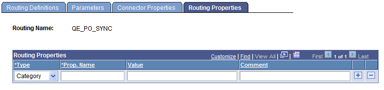
To add routing property name/value pairs:
Access the Routings-Routing Properties page ( and click the Routing Properties tab).
From the Type drop-down list box, select a property type. The options are:
Category.
Ident.
Search.
In the Prop. Name field, enter a name for the property.
(Optional.) In the Value field, enter a value for the property.
(Optional.) In the Comment field, enter a comment or description for the name/value pair.
Click the Add a Row button (+) to add additional rows and property name/value pairs.
Click the Save button.