 Understanding Workflow Maps
Workflow maps, also known as Navigator maps, are visual representations of your organization's business processes. Maps are necessary to all workflow processes, and they can also be used as navigational aids for end users.
This chapter provides overviews of workflow maps and map hierarchies and discusses how to:
Define maps.
Add map objects.
Control text.
Add drawing shapes to maps.
Use other map display features.
Arrange objects on maps.
Set icon properties.
Understanding Workflow MapsThis section discusses:
Workflow maps.
PeopleSoft Navigator maps.
 Workflow Maps
Workflow maps, also known as PeopleSoft Navigator maps, are visual representations of your organization's business processes. Maps are necessary to all workflow processes, and they can also be used as navigational aids for users.
There are two types of workflow maps, each representing a different hierarchical level. The top-level map, known as a business process, represents broad areas of functionality. Business processes contain one or more activities, or subprocesses. Activities contain individual steps that represent the specific transactions that complete that activity.
When you create workflow maps, you first create basic maps (business processes and activities) as described in this chapter. As you continue with subsequent steps, you add workflow-specific elements—events and routings—to the activities. You need events and routings only in activities that are used as workflow tools, not in those that are used as navigation tools.
PeopleSoft Navigator MapsPeopleSoft Navigator is an alternative to the standard portal navigation. With PeopleSoft Navigator, users can see workflow maps and use them to access pages (but not external programs) that are represented within these maps.
PeopleSoft Navigator presents maps according to their hierarchical relationships. Users can browse the available maps and navigate to individual pages by clicking the step that represents the page. As users move from map to page and back to map, the Navigator tree remains visible on the left-hand side of the screen:
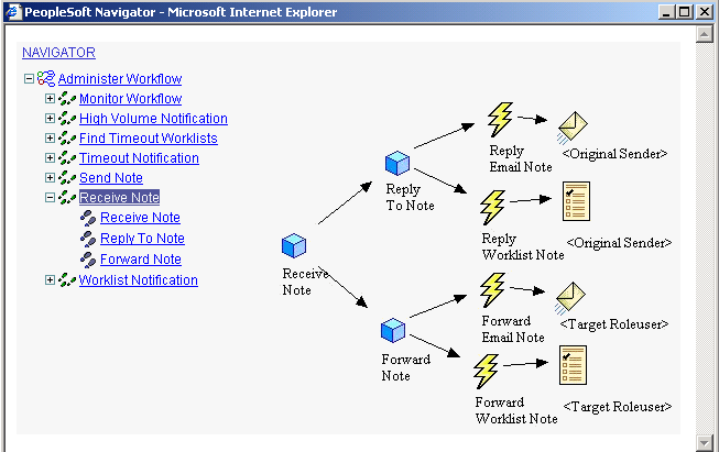
PeopleSoft Navigator
You control which maps are visible in PeopleSoft Navigator by defining a Navigator homepage: a top-level business process that greets the user when PeopleSoft Navigator is first accessed. Users can access only the maps that are hierarchically related to this homepage.
Understanding Map HierarchiesThis section discusses:
Map hierarchies.
Map icons.
Business processes.
Activities.
Map Hierarchies
PeopleSoft Workflow uses three hierarchical levels. The first two levels, business processes and activities, are both maps: graphical representations of the relationships between the component objects (other maps or steps).
The third level, steps, are not maps. Steps are elements within activities and represent the level at which the user interacts directly with application pages.
Business processes and activities are both freestanding definitions that you can open in PeopleSoft Application Designer and include in projects. Because business processes include icons for other maps (activities or other business processes), create these lower-level maps before you add them to a business process. You can develop in a top-down approach by creating the lower-level maps from the Business Process Designer directly.
Steps are not freestanding definitions in PeopleSoft Application Designer; they exist only within a particular activity. You create steps as you define an activity.
Note. PeopleSoft Workflow and PeopleSoft Navigator applications require all three levels: all activities must belong to business processes. Activity guides, on the other hand, do not involve business processes. Activity guides are built from standalone activities and their component steps. A setting in the Activity Properties dialog box identifies the activity as being used in an activity guide.
Map Icons
The following table presents the basic map elements.
Business ProcessesA business process is a graphical representation of the relationships between related activities. Arrows show the relationships between the activities, indicating the proper chronological sequence.
ActivitiesActivities that are intended only for end users (in PeopleSoft Navigator or in activity guides) typically include only steps that correspond either to application pages or to external programs.
When you incorporate workflow, activities also include events and routings. Events represent specific transactions that can occur in the page that is connected to the event. Routings represent notifications that are triggered by that event.
For example, there are several possible events on a page where managers approve orders. The manager can approve or deny the order or send the order back to the employee for changes. Each event requires routings to inform the next person in the chain (a buyer, an additional approver, or the employee who submitted the original order) about what must happen next.
The following map shows an activity with workflow routings:
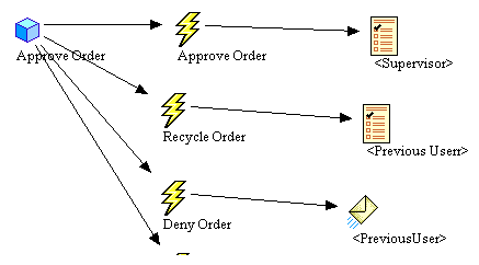
Activity with workflow routings
Defining MapsThis section provides an overview of map definition, lists common elements, and discusses how to:
Create a new map.
Define business process properties.
Define activity properties.
Understanding Map Definition
Create maps using PeopleSoft Application Designer. After creating the map, add items and establish the attributes of and relationships between those items.
Because maps are freestanding definitions in PeopleSoft Application Designer, use the standard techniques for opening, saving, deleting, renaming, adding to projects, printing, and so on.
Common Elements Used in This Section
|
Enter a description to appear in the dialog boxes that list this type of map. If you leave this field blank, the map name appears by default. This field is language-sensitive; the map name is not. If you intend to translate this object, supply a value for this field. |
|
|
Owner ID |
To track definition owners, enter an appropriate value. |
Creating a New MapTo create a new map:
In PeopleSoft Application Designer, select File, New.
In the New scrolling list, select the map type: Activity or Business Process.
Click OK.
Add the icons required to represent the activity or business process.
If you’re creating a business process, the icons represent other maps, activities, and possibly other business processes. When you add these types of icons to the map, you can specify an existing activity or business process that the icon represents, or you are prompted to create a new one.
Even if you do not save the business process on which you are working, the new activities or business processes that you created are saved to the database. Arrange the icons in a logical and visually informative way.
If appropriate, add modeling symbols, drawings, arrows, text, or other graphic elements to the map. These elements are useful primarily in maps that are visible in PeopleSoft Navigator. They do not affect workflow processing, nor are they visible in activity guides.
Connect the activities, decision points, and subprocesses in the appropriate order:
Click the Link button.
Click the two objects sequentially.
An arrow appears, pointing from the first object to the second.
The links between steps only clarify the flow of work. They do not directly determine the order of the steps, which you specify when you set the properties for individual icons in the maps. However, if you've enabled automatic sequencing in the activity properties, the default step order is based on the links.
Define the properties of the map.
Define the properties of the icons on the map.
Save the map.
Defining Business Process PropertiesTo define the properties of a business process:
Open the business process in PeopleSoft Application Designer.
Open the Business Process Properties dialog box:
Right-click in the map (but not on an item in the map).
Select Definition Properties.
The General tab in the Business Process Properties dialog box appears.
Set the properties on the General tab.
Set the properties on the Use tab.
A Navigator homepage is the high-level business process that a user sees immediately after accessing PeopleSoft Navigator. A user's homepage settings are established on the User Profile and Permission List pages. To make this business process available as a homepage, select the Can be used as a Navigator home page check box.
Click OK to accept the settings.
Save the business process.
Defining Activity PropertiesTo define the properties of an activity:
Open the activity in PeopleSoft Application Designer.
Open the Activity Properties dialog box.
Right-click in the map (but not on an item in the map).
Select Definition Properties.
The General tab in the Activity Properties dialog box appears.
Set the properties on the General tab.
Set the properties on the Use tab.
The Use tab includes options for automatically sequencing steps and for enabling end-user-facing activity guides.
After you add steps to an activity, arrange them into a logical sequence using connecting arrows, and assign each step a number. If you select Automatically sequence steps, the step numbers are automatically assigned when you save the activity. The step numbers are based on the order in which you connect the arrows. This is an efficient way to order the steps.
Select Activity Guide if you’re creating a map to use as the basis for an end-user-facing activity guide.
Note. Normally, an activity that you use in a workflow application isn’t reused as an activity guide. Instead, you create activities specifically for activity guides.
Click OK to accept the settings.
Adding Map ObjectsThis section provides an overview of toolbar buttons and discusses how to:
Add icons to maps.
Connect icons within a map.
Add images to maps.
Arrange objects on maps.
Set icon properties.
Control text.
Add drawing shapes to maps.
Use other map display features.
Understanding Toolbar ButtonsUse toolbar buttons to add icons and connecting lines to maps. Different toolbars (and therefore different map objects) are available for business processes and activities.
This toolbar provides the basic components of a business process, including activities and the lines that link them. This toolbar is visible only when a business process is the active window.
This toolbar provides the basic components of an activity, including steps, workflow events, and workflow routings. This toolbar is visible only when the active window displays an activity.
This toolbar provides additional buttons for creating icons to graphically enhance maps. Some of the icons are informational only; those that are functional have exact equivalents in either the Business Process or the Activity toolbar. This toolbar is visible when either a business process or an activity is the active window in the workspace.
This toolbar is visible when either a business process or an activity is the active window in the workspace.
Normally, you add an object to a map by clicking the object on the toolbar and clicking the location on the map. Some of the drawing tools, however, involve extra clicks on the map. For example, to draw a line, first click the Line button as you click any other button. To draw the line on the map, click once at the beginning of the line and again at the end of the line.
This toolbar contains options for aligning objects on several different axes.
|
|
Click the Align Top button to arrange all selected objects so that they are aligned at the top of the base position object. |
|
|
Click the Align Middle button to arrange all selected objects so that they are aligned at the middle of the base position object. |
|
|
Click the Align Bottom button to arrange all selected objects so that they are aligned at the bottom of the base position object. |
|
|
Click the Align Left button to arrange all selected objects so that they are aligned at the left-hand side of the base position object. |
|
|
Click the Align Center button to arrange all selected objects so that they are aligned at the center of the base position object. |
|
|
Click the Align Right button to arrange all selected objects so that they are aligned at the right-hand side of the base position object. |
This toolbar contains options to move objects in front of or behind each other.
|
|
Click the Front button to move the selected object in front of any overlapping objects. |
|
|
Click the Back button to move the selected object behind any overlapping objects. |
|
|
Click the Forward button to move the selected object in front of the overlapping objects that are immediately in front of it. |
|
|
Click the Backward button to move the selected object behind any overlapping objects that are immediately in front of it. |
These are actual workflow objects, representing transactions that trigger workflow (events) and the medium through which the trigger sends work to the recipient (routings). You normally add these objects to activities after completing the basic maps.
The following graphic presents the events and routings icons:
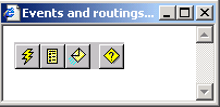
Events and routings icons
Adding Icons to Maps
Click the toolbar button representing the icon that you want to add.
Click the map where you want to place the icon.
In most cases, the icon is added to the map when you click. If you're adding an icon for an activity, business process, or transaction, however, the Select Definition dialog box appears.
In the Select Definition dialog box, select the specific activity, business process, or service operation definition that the icon represents.
Click the Select button to finish placing the icon on the map.
Connecting Icons Within a Map
To connect icons within a map:
Click the Link button on the toolbar.
You must use the link tool to connect icons; do not use arrows or other drawing objects.
Click the icon where the link starts.
The icon must be a linkable definition. As you pass the cursor over different parts of the map, its appearance changes to indicate whether you’re over a linkable definition:
A plus sign indicates that you are not over a linkable definition.
A plus sign within a circle indicates that you are over a linkable definition.
Click the icon where the link ends.
This click completes the link, and an arrow from one object to the other appears. Even if you relocate objects on the map, the link stays connected to both objects.
To cancel without completing the link, right-click.
(Optional) Modify the shape of the link.
To create angles at the same time that you create the link, make one or more intermediate clicks where you want the line to bend. You can add multiple angles. However, you must always end the line with a linkable definition.
Change the angle by clicking the connector line, selecting the angle anchor, and moving it.
To create an angle in an existing link, select the link, press and hold the Ctrl key, and click where you want to create an angle anchor. You can then move the anchor as described previously.
Adding Images to MapsTo add an image to a map:
Click the Image button on the toolbar.
Click on the map where you want to place the image.
Right-click the bitmap and select Change Bitmap.
The Select Image dialog box appears.
Select the image file.
Click OK.
The selected image replaces the default bitmap.
Note. The Select Image dialog box lists all of the images that are stored in the PeopleSoft database. If the Show Only Workflow Images check box is selected, the list includes only images that have the Used in Workflow property set in the image definition properties. If the Show Only Workflow Images check box is cleared, the list includes all images that can be rendered in the Microsoft Windows environment. Because Graphics Interchange Format (GIF) files cannot be rendered in Windows, they do not appear.
Table of Default Workflow Images
To replace the PeopleSoft default images for new or existing maps, you can add new images to the Image Catalog using the same names, as in the following table:
|
Type |
Image Name |
Toolbar Name |
|
Activity |
PT_WFD_ACTIVITY |
PT_WFD_TBACTIVITY |
|
Business Process |
PT_WFD_BUSPROC |
PT_WFD_TBBUSPROC |
|
Step |
PT_WFD_STEP |
PT_WFD_TBSTEP |
|
Batch |
PT_WFD_BATCH |
PT_WFD_TBBATCH |
|
Manual Process |
PT_WFD_MANUALPROC |
PT_WFD_TBMANUALPROC |
|
Transaction Same DB |
PT_WFD_SAMEDB |
PT_WFD_TBSAMEDB |
|
Transaction Other DB |
PT_WFD_OTHERDB |
PT_WFD_TBOTHERDB |
|
Transaction Outside Firewall |
PT_WFD_OUTSIDEFW |
PT_WFD_TBOUTSIDEFW |
|
Event |
PT_WFD_EVENT |
PT_WFD_TBEVENT |
|
Worklist |
PT_WFD_WORKLIST |
PT_WFD_TBWORKLIST |
|
|
PT_WFD_EMAIL |
PT_WFD_TBEMAIL |
|
Decision |
PT_WFD_DECISION |
PT_WFD_TBDECISION |
|
Bitmap |
PT_WFD_BITMAP |
PT_WFD_TBBITMAP |
Controlling TextThis section discusses how to:
Add standalone text to maps.
Format standalone text.
Change the position of icon text.
Adding Standalone Text to Maps
To add standalone text to maps:
Click the Text button on the Drawing toolbar.
Click the map in the location where you want to place the text.
A text box with the word text appears on the map.
Double-click the default text to select it.
Enter your own text.
Formatting Standalone Text
To format standalone text:
Right-click the text and select Item Properties.
The Text Properties dialog box appears.
Set the text properties.
Click OK.
Changing the Position of Icon TextTo change the position of icon text:
Click the text to select it.
Drag the text to its new position.
You might want to center caption text under the object that it describes.
Adding Drawing Shapes to MapsThis section discusses how to:
Add drawing shapes to maps.
Change the appearance of the drawing line.
Change the color and pattern of a drawing shape.
Adding Drawing Shapes to Maps
To add drawing shapes to maps:
Click a drawing shape button.
Draw the shape on the map.
The drawing method depends on which shape you’re drawing.
Modify the shape by dragging the handles to a new location.
Changing the Appearance of the Drawing Line
To change the appearance of the drawing line:
Double-click the shape to open the Properties dialog box.
Set the properties on the Line tab.
Click Transparent to make the line disappear. When you select this option for a line, only the arrowhead on the line remains visible.
Click OK to close the dialog box.
Changing the Color and Pattern of a Drawing Shape
Because lines and curves do not enclose a drawing area, this procedure applies only to rectangles and ellipses.
To change the color and pattern of a drawing shape:
Double-click the shape to open the properties dialog box.
Set the properties on the Fill tab.
For a solid fill (no hatching), select a foreground color to fill the shape.
To prevent the drawing from covering other shapes behind it, select Transparent Fill.
For a patterned fill, select both a foreground and background color, and select a hatch pattern.
Select Transparent Background to apply hatches while leaving the fill transparent. The pictures of the hatching options show the color scheme that you’ve selected.
Click OK to close the dialog box.
Using Other Map Display FeaturesThis section provides an overview of other map display features and discusses how to:
Control the size of the map display (the zoom).
View the grid.
Resize the grid.
Activate the snap-to grid.
Navigate between a business process and its constituent maps.
Understanding Other Map Display Features
When you create a map, additional display options help you control the design environment. For example, maps have an optional grid to help you align objects precisely on the map. You can view or hide the grid, define its size, and specify whether objects snap to the grid intersections when you place or move them.
Controlling the Size of the Map Display
To change the display (zoom) size of the map:
Select View, Zoom.
Select the level of magnification.
Click OK.
Viewing the GridTo view or hide the grid, select View, Grid Visible. This menu item is a toggle command. When the grid is visible, a check mark appears next to the menu item. By default, the grid is visible.
Resizing the Grid
To resize the grid:
Select Edit, Grid.
The Window Grid dialog box appears.
Select how much space (in pixels) should appear between the lines of the grid. Select the width (the number of pixels between the vertical lines) and the height (the number of pixels between the horizontal lines).
Click OK to close the dialog box.
If the grid is visible, it redisplays its grid lines based on the new settings. If the grid is not visible, the new settings still take effect, although you can’t see them.
Activating the Snap to GridWhen the Snap to Grid feature is active, PeopleSoft Application Designer positions all objects so that they each have a corner at an intersection in the grid. The grid doesn’t have to be displayed for this option to work. This menu item is a toggle command. When the option is selected, a check mark appears next to the menu item. By default, this option is not selected.
Navigating Between a Business Process and Its Component MapsA business process comprises lower-level maps. These lower-level maps, whether activities or other business processes, are freestanding objects in PeopleSoft Application Designer. It’s convenient to open the lower-level maps directly from the business process map, rather than using the standard File, Open command.
To access a map that is part of a business process, double-click the icon for the lower-level map within the business process, or right-click the icon and select View Definition.
Arranging Objects on MapsThis section discusses how to:
Move objects on maps.
Delete objects from maps.
Change the display bitmap of an existing icon.
Align multiple objects visually.
Move objects in front of or behind each other.
Moving Objects on MapsTo move objects on maps:
Select the object.
Handles appear around the object.
Drag the object to a new position.
When you drag an object, caption text moves with it. You can, however, select or move just the text to reposition it relative to its object.
If an object is linked to other objects, the lines representing links move with the object.
Use the Snap to Grid feature to align the object to the grid or deactivate the Snap to Grid feature for free-form placement.
Deleting Objects from MapsTo delete objects from maps:
Select the object to delete.
Press Delete.
Changing the Display Bitmap of an Existing IconTo change the display bitmap of an existing icon:
Right-click the icon and select Change Bitmap.
The Open dialog box appears.
Select the image file.
Click OK.
The selected image replaces the default bitmap.
Note. The Open dialog box for Change Bitmap lists only images that are Microsoft Windows-compatible. Also, when the system saves the activity or business process definition, it automatically generates a JPEG file of it so that it can be viewed in PeopleSoft Navigator (in the browser).
Aligning Multiple Objects VisuallyTo align multiple objects visually:
Decide on a base position object; you’ll move other objects in line with this base position object.
Press Shift while selecting the objects that you want to move.
Select the base position object last. To deselect an object, continue to press Shift and select the object again.
Click the appropriate button in the Alignment toolbar.
Moving Objects in Front of or Behind Each Other
To move objects in front of or behind each other:
Select the objects that you want to move in front of or behind another overlapping object.
Click the appropriate button on the Layering toolbar.
Setting Icon PropertiesThis section provides an overview of descriptive icons and discusses how to:
Set properties for descriptive icons.
Set properties for step icons.
Set attributes for step icons.
Understanding Descriptive Icons
Both business processes and activities can include descriptive icons. These icons typically do not have associated workflow processing; they are useful primarily if the map will be visible through PeopleSoft Navigator.
Note. Even though the Activity icon does not have any associated processing, it must be included in the business process to establish the relationship between the activity and the business process. That relationship is necessary for proper workflow processing.
Setting Properties for Descriptive IconsTo set properties for descriptive icons:
Right-click the descriptive icon and select Item Properties.
The Properties dialog box appears. Depending on the type of icon, the title bar reads Business Processes Definition, Activity Definition, or Description Symbol Definition.
Enter information in the dialog box.
The text that you enter in the Name field identifies the icon and, by default, appears as the display text under that icon. To display different text under the icon, enter it in the Icon Descr text box. Include line breaks in the text by pressing the Enter key.
Click OK to close the dialog box.
Setting Properties for Step IconsSet properties for the steps in an activity to associate the step with the proper page or external program and to establish the correct sequence of steps within the activity.
To set properties for step icons:
Right-click the step icon and select Item Properties.
The Step Definition dialog box appears.
Enter descriptive information about the step.
Enter the step and path numbers to place this step into the activity’s flow.
The Step Number and Path Number boxes order the steps in this activity. When the user always completes the same steps in the same order, specify the order of the step in the Step Number box and leave the number 1 in the Path Number box. The first step is step 1; the second is step 2.
When the user performs different tasks along the way, define multiple step paths. Start numbering the steps from step 1, staying on path 1 until you reach the first point at which a user has options. For each step that might come next, use the next consecutive step number, but a different path number, for each one. All of the steps should have the same step number sequence, but a different path number value.
If a user-facing activity guide based on this map is available, you might want to make the more common path the default path. Select Default Step for the step that you want the activity guide to take when a user progresses through the activity.
You can avoid the manual sequencing of steps if you use the automatic step sequencing options that are available in the property sheet for the activity. However, always review the sequence created by automatic numbering to verify that the sequence is correct.
(Optional) Click Activity Guide.
This button is available only if you have marked this as an activity guide in the activity properties. The Step Internet Client Attributes dialog box appears. If this map is an activity that will be used in an activity guide, enter the necessary information in this dialog box.
Setting Step AttributesThis section discusses how to set step attributes.
Use the Step Attributes dialog box to select the page or program that the system starts when a user selects this step and the action mode that is used to open the page.
To set step attributes:
On the Step Definition dialog box, click the Attributes button.
Specify whether the user completes this step on a PeopleSoft page or from an external program.
When you select Page or External Program, the appropriate section of the dialog box becomes available. If this is an activity guide and you’ve marked the activity guide option in the activity properties, you must select Page.
Provide directions for starting the page or external program.
If a user performs the step by completing a PeopleSoft page, select the page from the list boxes in the Processing Page group box.
In the Action drop-down list box, select the type of activity that the user must perform on the database: Add,, Update/Display, Update Display/All, or Correction. When a user selects this step, the system displays the specified page in the specified action mode.
Note. You must assign a page to a menu before you create a step that navigates to it.
If users perform the step using an external program, select the program name and its working directory from the External Program group box. The program name must be the name of the executable file, followed by command line parameters, if appropriate. When a user selects this step, the system starts the specified program.
Note. If this step is the first step in its activity (step 1 path 1) and the activity has an associated worklist, the system can pass additional parameters to the external program from the worklist record.
Click OK in the Step Attributes dialog box.
Click OK to close the Step Definition dialog box.